

The phone:400-082-0829
email:info@bekannter.cn
Address: Building 3, Phase II, Thousand Talents Planning Industrial Park, Yuyao, Ningbo, Zhejiang


Comparison of three technical schemes:
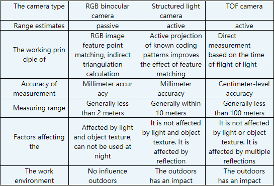

Figure 1. Birkenstock's self-developed tandem hybrid six-axis robot

Figure 2. Birkendt independently developed robot controller and structured light 3D camera
2) Robot hand-eye calibration: The hand-eye calibration method based on double quaternion is adopted. On this basis, the observed data outliers are filtered by using the spinor consistency theorem to improve the calibration accuracy. For the rigid body transformation of spatial lines, it is more efficient to use the unit diquaternion to compute the transformation than to use the homogeneous matrix directly. Meanwhile, for continuous rigid body transformation, it can be expressed as multiplication of two unit diquaternions, which is similar to homogeneous matrix. The rigid body transformation in three dimensional space can be expressed compactly by using the unit double quaternion. According to the spinor consistency theorem, the error formula is adopted to eliminate the outliers.

FIG. 3 Schematic diagram of hand-eye calibration

FIG. 4 coordinates of spinor and Pluker of the line
3) Point cloud simplification: A large number of point clouds are simplified based on enveloping box and random sampling method, and effective band point cloud images related to grasping targets are retained.
4) Point cloud denoising: Due to noise or distortion points, points with large errors and points with large jumps will inevitably occur. Gaussian filter is used to remove the noise of the target relative point cloud image.
5) Point cloud segmentation: Edge, region, mixture and cluster based methods are adopted to complete the segmentation of grabbing target and surrounding field and scenic spot clouds, so as to make the characteristics of grabbing target point cloud clearer and more obvious.
6) Pose estimation: According to the gradient information of the color image and the normal vector of the object surface, a specific algorithm is used to find the best pose of the target to be captured.

FIG. 5 Point cloud segmentation model based on image threshold

FIG. 6 Point cloud segmentation model of perspective transformation

Figure 7. Original image captured by camera

FIG. 8 Depth image acquired by camera
3D vision system is mainly divided into five functional modules: system calibration module, point cloud processing module, communication module, display module and file management module. Currently, the 3D vision system developed by The Birkenstock Robotics Institute can be applied to automatic packaging, stacking, loading and unloading of machine tools, welding and other aspects.
"Flexibility" is a new requirement for industrial robots in the new era. For the task of grasping, "flexibility" means that no matter what workpiece appears at what position of the workbench, the robot can automatically identify and complete grasping. Visual AIDS are the key to solving the problem. Using the rich information of the vision sensor, the robot can recognize the object and judge the position and attitude of the object relative to the robot. Then the grab pose is generated according to the object, and the grab task is performed after the motion planning is completed. Among them, the recognition and location of the target object is the precondition of successful capture. Motion planning is the key to realize flexible grasping without teaching. However, the Birkenstock robot has gradually realized this requirement, and is constantly exploring deeper technical fields.
The phone:400-082-0829
email:info@bekannter.cn
Address: Building 3, Phase II, Thousand Talents Planning Industrial Park, Yuyao, Ningbo, Zhejiang

Follow Us